


I've done quite a bit of experimentation and testing with various
home made dipoles for 24dBi Conifer dishes,
and have managed to increase the performance of the dish.
Trevor Marshall has a
webpage with information
about using a biquad as a feed on a Primestar satellite dish, with very good
results. I decided to try using a biquad as a feed on a 24dBi Conifer dish,
to see if I could improve the performance of it of the dish.
Note that the photos on Trevor Marshall's
webpage
do not clearly show the construction of the biquad - particularly the way
in which the quad is attached to the coax. Numerous people (including myself)
have constructed biquads incorrectly, based on his photos, and found that
they perform very poorly.
Use the photos of my biquad below, and refer to the websites listed in the
references section at the bottom of this page
for more information on the correct construction of the biquad.
I used the following bits and pieces:
- 123x123mm square section of blank PCB
- 50mm length of 1/2" copper pipe
- short length of CNT-400 or LMR-400 low loss coax (~300mm long)
- 250mm of 2.5mm2 copper wire (approx 1.5mm diameter)
- N connector
I've also heard of people using CDROM as the reflector, as the foil on it will certainly reflect microwaves.
Cut a square piece of blank printed circuit board, 123x123mm.
Note that Trevor Marshall recommends a size of 123x123mm if using the biquad as a stand-alone antenna, while 110x110 is optimal if using it as a feed for a large dish.
He also recommends attaching some lips to two sides of the reflector, to reduce radiation from the rear lobes.
Use some steel wool to remove any tarnish and polish it up. Cleaning the copper in this way will make it easier to solder.

blank printed circuit board
Cut a 50mm section of copper pipe, and file both ends smooth. Using some sandpaper and/or some files, polish up the copper pipe (including the inside of the copper pipe, to ensure a good connection with the coax braid).

the dimensions of the copper pipe
Cut a notch into one end of the copper pipe, removing approx 2mm from half the circumference.

a short secion of copper pipe, notched at one end
Drill a hole in the centre of the blank PCB so that the copper pipe is a tight fit in the hole. I found a reamer to be very useful for enlarging the hole to the correct size.

making a hole in the centre
Insert the copper pipe into the hole, with the notched end on the copper side of the blank PCB. The copper pipe should be protruding approx 16mm through the hole, measured on the copper side of the PCB.

insert the copper pipe into the reflector
Solder the copper pipe to the PCB, to ensure a good physical and electrical connection.

solder the copper pipe to the PCB
Quite a bit of heat is needed, due to the thickness of the copper pipe, and an electrical soldering iron probably won't be able to deliver sufficent heat. I found a small gas torch works quite well.
The element is made from a length of copper wire, bent into the appropriate shape.
Note that the length of each "side" should be as close to 30.5mm as possible (measured from the centre of the copper wire to the centre of the copper wire), which is a quarter of a wavelength at 2.4GHz

the shape and dimensions of the element
I had some offcuts of electrical power cable lying around, and found that 2.5mm2 power cable had a diameter of approx 1.6mm - a little bigger than the 1.2mm that Trevor Marshall specifies, but didn't think it would make a significant difference to the performance of the biquad.

recycling power cable offcuts
Remove the insulation, measure and cut a 244mm length the copper wire, and straighten it as best as you can.

straighten the wire
Measure the mid-point of the wire, and make a 90 degree bend. The bend should be quite sharp and pronounced.

90 degree bend
Measure the midpoints of each half, and make two more 90 degree bends in the wire, so that it looks like that shown in the photo below.

another two bends
Once again, measure the midpoints of each section, and make some more 90 degree bends, resulting in what is shown below.

bend it some more...
Do the same to the other side, resulting in the biquad shape.

make it symetrical...
Clean up all your bends, and ensure each side of the element is as straight as possible, and as close to 30.5mm as possible.
Note that you may need to trim a small amount off each end of the wire to achieve this.
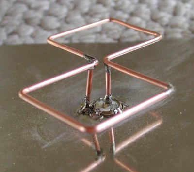
The element must now be attached to the reflector. Note that only the two "ends" of the copper wire are to be attached to the copper pipe - the centre of the copper wire must not touch the copper pipe (hence the notch which was cut into the end of the copper pipe.
The copper wire element should be approximately 15mm away from the reflector. Testing antenna performance while varying the spacing between the copper wire element and the rear reflector indicates that a spacing of approx 15mm provides the lowest SWR (test results available here).

the element soldered onto the copper pipe
Strip approx 30mm of the outer sheath from the end of the coax.

strip the outer sheath
Fold the braid back over the outer sheath, and trim the centre conductor, so that about 4mm is protruding.

fold the braid back, trim the centre conductor
Insert the braid into the copper pipe, so that the end of the centre conductor lines up with the extreme end of the copper pipe, and solder the centre of the element to it, ensuring the centre of the element is not in contact with the copper pipe. Refer to some of the additional photos below for details.

solder the centre conductor to the element

another view
Note that the feed between the rear reflector and the biquad element needs to be shielded. Using coax to feed the biquad element directly, and positioning the coax inside the copper tube achieves this.
Use of bare conductors as a feed between the reflector and biquad element results in a radiating feed (such as this one), which will have a detrimental effect on the biquad's performance.
I used a coax crimper to crimp the end of the copper pipe onto the coax. This ensures that the coax would not move inside the copper pipe.

the copper pipe crimped onto the coax

the completed biquad
Now terminate the other end of the coax with an N connector.
If desired, you can add spacers at each end of the element, to ensure the element doesn't move in relation to the reflector. Refer to my double biquad page for more details on making spacers to support the element.
If you intend to mount the biquad outside, I'd recommend you place it into a weather-proof enclosure, to prevent corrosion, and to prevent water ingress into the coax.
Numerous people have used small tuppaware containers successfully.
This can be achieved by drilling a hole in one side of the container, and pass the coax tail through the hole, leaving the biquad itself inside the container. Seal up the hole for the coax with some silicone, and your biquad should be protected against the elements.
another view of the completed biquad
Some very rough initial testing using the biquad as a feed on a 24dBi Conifer dish looks very promising, with the signal strength being at least as as good as my home made Conifer dipole (I was holding the biquad at approximately the focal point of the dish, and hadn't even removed the Conifer dipole).
I also managed to get a marginal link to a 180 degree waveguide on an access point 10km away, using only the biquad by itself, connected to a 30mW RoamAbout wireless card.
Some more detailed testing with multiple antennas, including the biquad shown above, indicates the biquad has a gain of approx 11-12dBi.
A friend has access to some antenna test equipment, and performed some tests on the biquad featured on this page.
The azimuth plot (ie, radiation pattern) of the biquad is shown below, and shows a 3dB beamwidth of about 50 degrees.

azimuth plot of the biquad
A number of people have suggested the spacing between the element and the rear reflector should be a 1/4 wavelength (ie, 30.5mm) instead of 15mm. However, test results (such as these) indicate the SWR of the biquad is minimised when the spacing is about 15-17mm. Increasing the spacing to 30.5mm increases the SWR significantly, thus reducing the efficiency of the biquad.
For a higher-gain variation of the biquad that's virtually just as easy to build, have a look at the double biquad.
For information on connecting a biquad antenna to a wireless radio, have a look at the page on using wireless antennas.
When using a biquad to establish a link to another wireless device, you should ensure the polarisation of the biquad is the same as the antenna you are connecting to. Similarily, if establishing a link with two biquads, ensure they are both oriented for the same polarisation.
Failing to match the polarisation will result in significant signal loss.
 vertically polarised |
 horizontally polarised |
Changing the polarisation is just a matter of rotating the entire biquad antenna by 90 degrees.
The biquad antenna is not particularly directional, but has a fairly wide beamwidth.
The 3dB beamwidth for a biquad (without side lips) is typically about 40-50 degrees, thus making it ideal for any applications where you want fairly wide coverage.
The relatively wide beamwidth also makes a biquad very suitable for war-driving and stumbling, allowing you to pick up signals without having to align the antenna directly with the signal source.
While a directional antenna, such as a Conifer dish (3dB beamwidth of a 24dBi Conifer dish is approx 7 degrees), is better suited for point-to-point links, the narrow beamwidth of a Conifer dish requires more precision when aligning the antennas (the narrower the beamwidth, the less susceptible it will be to interferance from other sources). An antenna with a wider beamwidth, such as a biquad, doesn't require the same precision for alignment, thus making it easier to get a link working.
If you're one of those people who may not have all the tools required for building a biquad antenna from scratch, or you don't want to shop around for all the parts required, you can buy a DIY kit containing all components from WarDrivingWorld.
In November 2006, WarDrivingWorld sent me one of their DIY biquad kits to review. The kit contains all the pre-cut and pre-drilled parts required to build a biquad antenna.
For more infomation on this kit, including antenna comparision test results, read my review of the WarDrivingWorld DIY Biquad Kit.
sumber ; http://martybugs.net/wireless/biquad/
![]() Posted By Sameera Chathuranga
Posted By Sameera Chathuranga
Lorem ipsum dolor sit amet, consectetur adipisicing elit, sed do eiusmod tempor incididunt ut labore et dolore magna aliqua. Ut enim ad minim veniam, quis nostrud exercitation test link ullamco laboris nisi ut aliquip ex ea commodo consequat contact me
Thank You
![OPPO Joy [R1001] - White](http://www.bhinneka.com/Data/image_product/OPPO-Joy-[R1001]-White-SKU01214626_0-20140902134835.jpg "OPPO Joy [R1001] - White")

![TP-LINK N750 Wireless Dual Band Gigabit Router [TL-WDR4300]](http://www.bhinneka.com/Data/image_product/TP-LINK-N750-Wireless-Dual-Band-Gigabit-Router-[TL-WDR4300]-SKU00712872_0-20140417101429.jpg "TP-LINK N750 Wireless Dual Band Gigabit Router [TL-WDR4300]")

![ASUS Wireless-N Router [RT-N12HP]](http://www.bhinneka.com/Data/image_product/ASUS-Wireless-N-Router-[RT-N12HP]-SKU00113615_0.jpg "ASUS Wireless-N Router [RT-N12HP]")
![ASUS Fonepad 7 [FE170CG] - Mica Black](http://www.bhinneka.com/Data/image_product/ASUS-Fonepad-7-[FE170CG]-Mica-Black-SKU00614737_0-20140506151255.jpg "ASUS Fonepad 7 [FE170CG] - Mica Black")


![ASUS Wireless-N Router [RT-N10U B]](http://www.bhinneka.com/Data/thumbnail_product/ASUS-Wireless-N-Router-[RT-N10U-B]-SKU01112255-20140417090227.jpg "ASUS Wireless-N Router [RT-N10U B]")


![SAMSUNG Galaxy Camera 2 [GC200] - White](http://www.bhinneka.com/Data/thumbnail_product/SAMSUNG-Galaxy-Camera-GC200-White-SKU00314420.jpg "SAMSUNG Galaxy Camera 2 [GC200] - White")
![SANDISK Extreme II Desktop [SDSSDXP-120G-G26]](http://www.bhinneka.com/Data/thumbnail_product/SANDISK-Extreme-II-Desktop-[SDSSDXP-120G-G26]-SKU01213130.jpg "SANDISK Extreme II Desktop [SDSSDXP-120G-G26]")
![CORSAIR Memory Notebook 8GB DDR3 PC-10600 [CMSO8GX3M1A1333C9]](http://www.bhinneka.com/Data/thumbnail_product/CORSAIR-Memory-Notebook-8GB-DDR3-PC-10600-[CMSO8GX3M1A1333C9]-SKU00911963-20140422104325.jpg "CORSAIR Memory Notebook 8GB DDR3 PC-10600 [CMSO8GX3M1A1333C9]")

![TP-LINK Outdoor Wireless Access Point [TL-WA7210N]](http://www.bhinneka.com/Data/thumbnail_product/TP-LINK-Outdoor-Wireless-Access-Point-[TL-WA7210N]-SKU01413236-20140513114348.jpg "TP-LINK Outdoor Wireless Access Point [TL-WA7210N]")


![ACER Iconia [W511] - (Non Docking)](http://www.bhinneka.com/Data/thumbnail_product/ACER-Iconia-[W511-]-(Non-Docking)-SKU00113506.jpg "ACER Iconia [W511] - (Non Docking)")
![ACER Iconia [W510] - (Non Docking)](http://www.bhinneka.com/Data/thumbnail_product/ACER-Iconia-[W510]-SKU01212580.jpg "ACER Iconia [W510] - (Non Docking)")
0 komentar:
Posting Komentar